The contact pattern of gears reveals the points at which power is transmitted when the tooth flanks mesh. If the contact pattern in the test deviates too far from the specified optimum contact pattern, the gear is readjusted or rejected. Conventional testing with spotting paste is time-consuming and cleaning-intensive, and only reflects the sum imprint. The newly developed thermal inline contact pattern inspection from edevis, on the other hand, inspects the contact pattern in the load test rig quickly, residue-free, fully automatically and can evaluate each tooth pair individually if required.
The application:
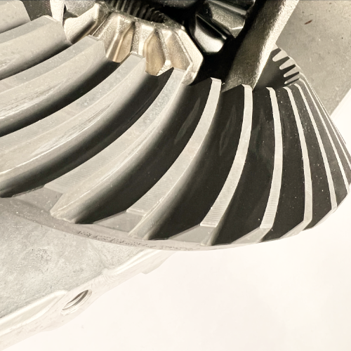
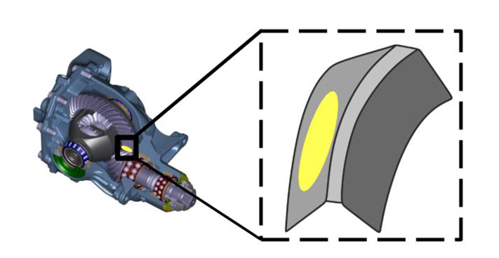
In a fully automated transmission manufacturing facility, the rear axle gears of a car manufacturer are to be subjected to a contact pattern inspection. In an inline inspection station, the gears are loaded with a defined torque, creating a thermal fingerprint between two teeth. An infrared camera is used to visualize and automatically evaluate the contact pattern.
The savings:
The rationalization benefits of thermographic processes are great. Instead of the previous contact pattern inspection using spotting paste, which requires the application of paint and subsequent cleaning, infrared thermography allows the contact pattern to be determined fully automatically in short cycle times and without auxiliary materials.
The task:
The task was to develop and implement an inspection technique to determine the contact pattern. The gears rotate at up to 400 rpm and sharp and repeatable images of each gear tooth must be captured despite the movement. This requires the use of very powerful infrared cameras that work with relatively short exposure times and fast image sequences. During the test, the gear unit had to be rotated about five times in order to cover all possible tooth pairings mathematically. The total cycle time including insertion, rotation and measurement was 28 seconds.
The challenge:
The teeth can look very different from gear to gear because they have different shapes and different (e.g. ground or bonded) surfaces. As with a stroboscope, the camera must capture the tooth at exactly the right time and in the right angular position. Ambient reflections must be excluded in the process.
Solution:
To be able to evaluate all tooth combinations correctly, several images are taken of each tooth. By changing the direction of rotation, it was ensured that the teeth could be examined on both the traction and thrust flanks. The images were taken using a Stirling-cooled infrared camera with large, light-sensitive pixels. The torque applied to the test rig was transmitted to the camera in real time, allowing the calculation of differential images without and with load.
The Machine Learning:
The key success factor of the project was “machine learning,” which allows the inspection software to work intelligently and autonomously sort out defective parts. First, the software must be taught to segment the tooth of a gear and uniquely identify it while it is running. With an adjustable trigger delay, the infrared camera made it possible to select the right time at which the teeth are optimally detected. Which tooth profile is still within the tolerance range of the prescribed contact pattern and which is not, is learned by the inspection software through a teach-in procedure. First, gear samples are read in as master images, which serve as a reference for the contact pattern inspection. The tolerance range for how a measured contact pattern should look and how far it may deviate from the nominal condition is defined parametrically by the customer. Once the teach-in process has been completed, the contact pattern deviations are detected automatically and reliably.
The project planning:
Project planning at edevis could not be carried out completely in the in-house test laboratory, since the gearboxes can only be tested meaningfully under load. However, this hurdle could be partly compensated by experiences from previous projects at large automotive manufacturers. Parts of the order were developed in the laboratory situation and later verified under load, other parts directly at the customer’s site. The test bench development was carried out in close cooperation with the customer and the plant manufacturer.