01
Data Acquisition
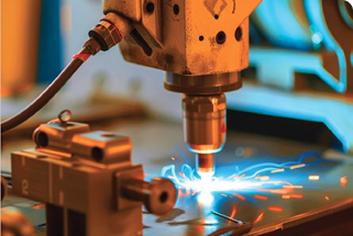
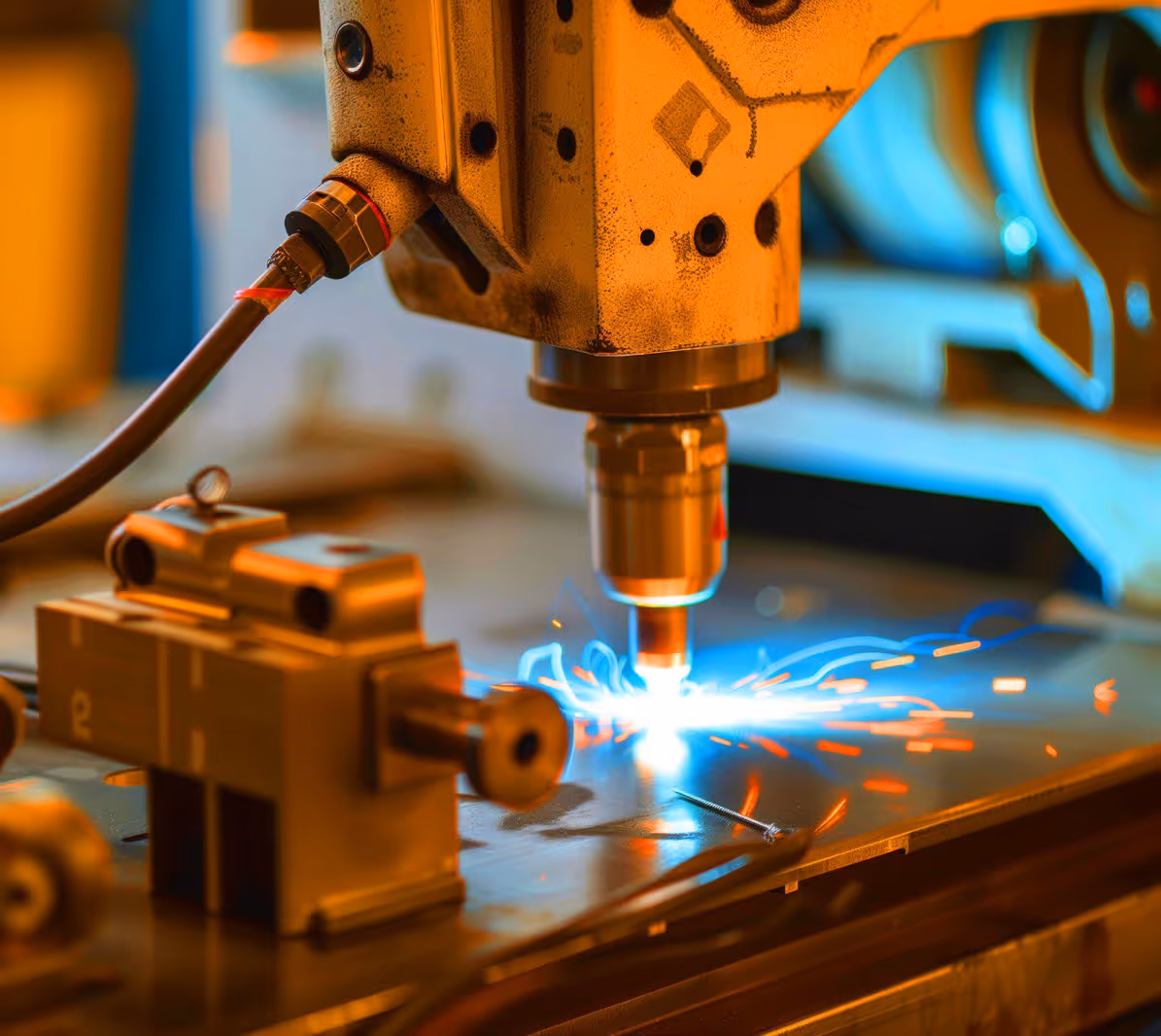
First, raw image data of the tooth flanks in the IR spectrum is acquired under various load conditions. These datasets form the basis for the subsequent difference calculation.
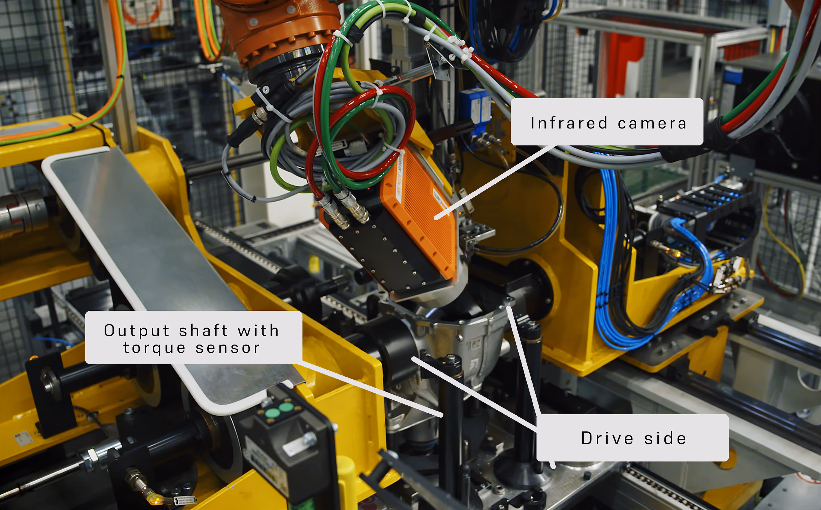
Watch videoGearboxes are key components in power transmission within mechanical engineering, automotive engineering and power generation. Deviations in tooth flank contact lead to increased wear, noise and power losses – sometimes with serious consequences for reliability and service life. This is where the thermographic contact pattern inspection developed by edevis comes in: it records load-induced temperature patterns on tooth flanks non-contact and without the use of additives, thereby ensuring that power transmission takes place precisely at the defined contact point. The thermographic contact pattern inspection can be integrated into the manufacturing process as an automated quality control measure.
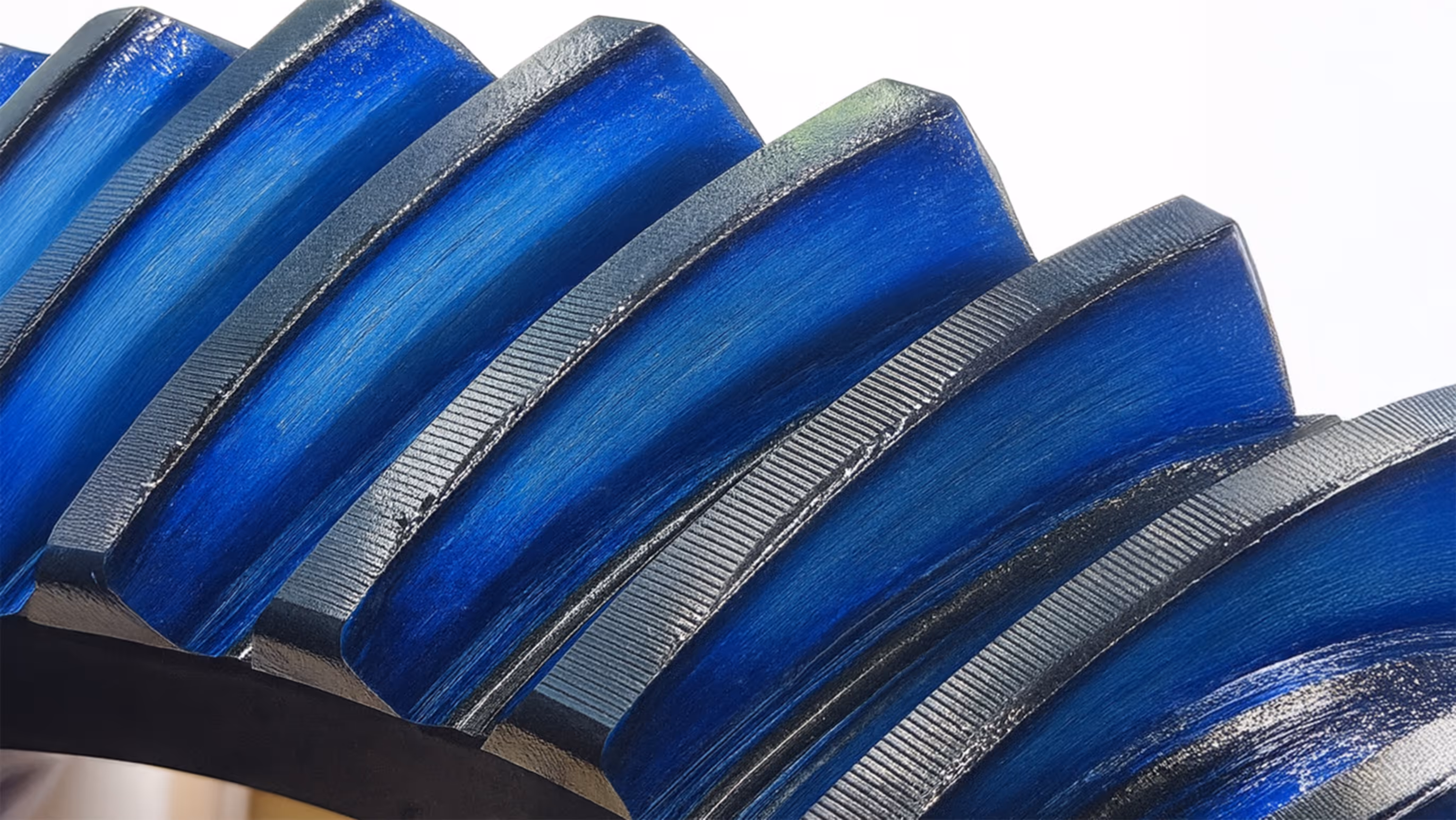

To date, particularly in the case of hypoid gearboxes, tooth contact testing has been carried out by applying dye and then assessing the results manually. To do this, a thin layer of dye (dye paste or varnish) is applied to the tooth flanks to be tested. When the gears are subsequently brought into mesh, the paint is removed at the points of contact through pressure or abrasion. The resulting image – for example, the displacement of an oil-resistant paste on the gearing – shows where the flanks are actually in contact. A specialist then visually assesses whether the position and size of the impressions correspond to the target condition.In the event of deviations, adjustments are made – for example, by retroactively shifting the gears relative to one another (e.g. using shims) or by proactively adjusting the manufacturing parameters. Furthermore, all paint residues must be removed without leaving any traces prior to commissioning.
However, the traditional contact pattern inspection using paint application has several disadvantages:
Each inspection process requires the application of dye, the joining of the parts and subsequent cleaning, entailing increased time and labour costs
The assessment is visual, often based on a cursory inspection. The result depends on the inspector's experience and interpretation.
The mark shows only the aggregate contact pattern; often, due to time constraints, the contact point is inspected on only a partial segment of the gear. Local deviations at individual contact points may be overlooked.
Manual ink application is difficult to integrate inline into automated production; 100% inspections are practically impossible to implement.
Uneven or incomplete ink application can distort the image. These limitations create a need for a more objective, efficient method, which is where thermographic contact pattern inspection comes in.
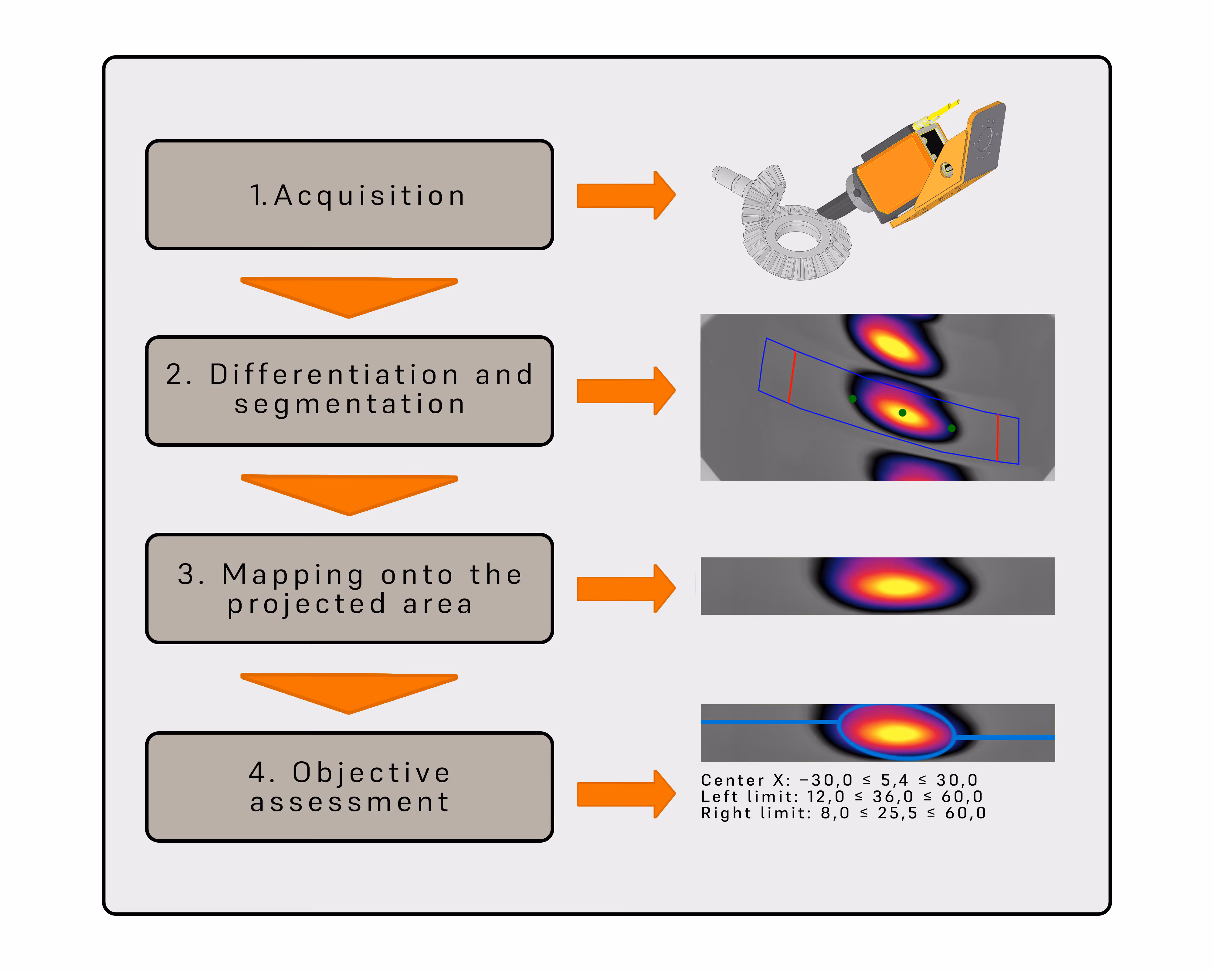
First, raw image data of the tooth flanks in the IR spectrum is acquired under various load conditions. These datasets form the basis for the subsequent difference calculation.
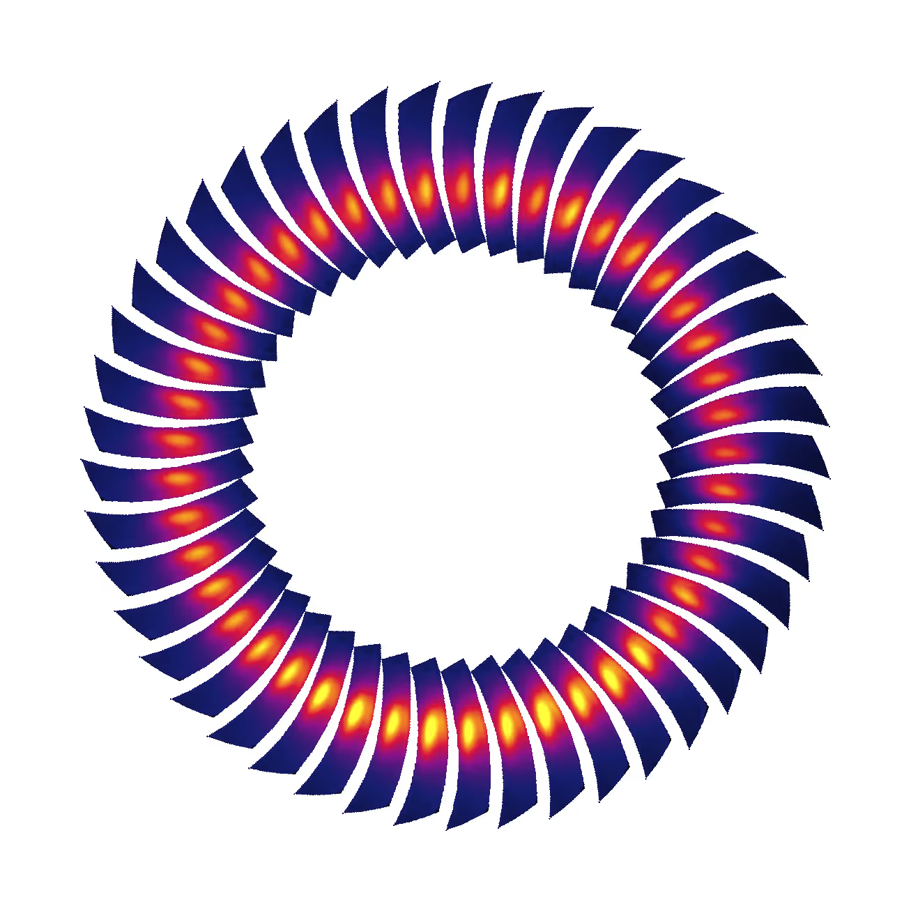
Watch videoIn the next step, the measurements are compared. A difference calculation is used to eliminate background components, thereby revealing the temperature increases caused by contact. The difference images reveal the areas where the tooth flanks were actually in contact. This is followed by the segmentation of relevant areas: an algorithm identifies the contact areas within the region of interest (ROI) on the tooth flank and separates them from non-contact areas.
As the tooth flank appears distorted due to its curvature and the camera perspective, the segmented contact image is mathematically rectified. This geometric projection transfers the detected contact image onto a flat surface that corresponds to the actual tooth flank geometry. This allows the contact image to be analysed metrologically and compared with CAD data or target contours.
In the final step, the relevant parameters are automatically calculated from the rectified surface. These include, in particular, the position of the centre of gravity of the contact point relative to the tooth flank. Based on defined target values and tolerance limits, the algorithm determines whether the gear meets the requirements.


We are happy to support you in finding the right solution for your contact pattern inspection requirements. Whether for research, series testing or individual special applications, our thermography technologies offer a wide range of possible uses. In a non-binding discussion, we will work together to determine which system best fits your application.
Our frequently asked questions — answered quickly and easily.